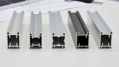



Choosing the right Aluminium Heatsink Profile is not simply a matter of selecting the largest available extrusion. It requires a clear understanding of heat generation, airflow, installation space, and production limits. A profile that looks impressive may still perform poorly inside a sealed enclosure. Thermal design begins with the actual application.
Thermal-management engineer Dr. John Parry offers a practical reminder: “A heatsink is only as good as the system around it.” This principle matters when comparing fin height, fin spacing, base thickness, and aluminium alloy. For many applications, 6063 aluminium provides a useful balance between thermal conductivity, extrusion quality, weight, and cost. However, alloy choice alone cannot guarantee reliable cooling. Airflow direction, contact pressure, thermal interface material, and mounting orientation can change the final result.
Measure the heat first.
A suitable profile should match the component’s wattage and permitted operating temperature. Engineers should also examine the available footprint, manufacturing tolerance, surface treatment, and expected service environment. Anodising may improve corrosion resistance and surface durability, while machining can improve contact flatness. These benefits may increase cost, so they deserve careful review.
Real-world testing remains essential. Calculate thermal resistance, then verify it with a prototype under realistic airflow and load. This step often reveals uncomfortable details, such as uneven contact or insufficient ventilation. I have seen designs fail because the fin pattern was selected from a catalogue without considering dust, fan performance, or assembly access. The “best” Aluminium Heatsink Profile is therefore not universal. It is the profile that delivers stable thermal performance, practical installation, and dependable long-term value.
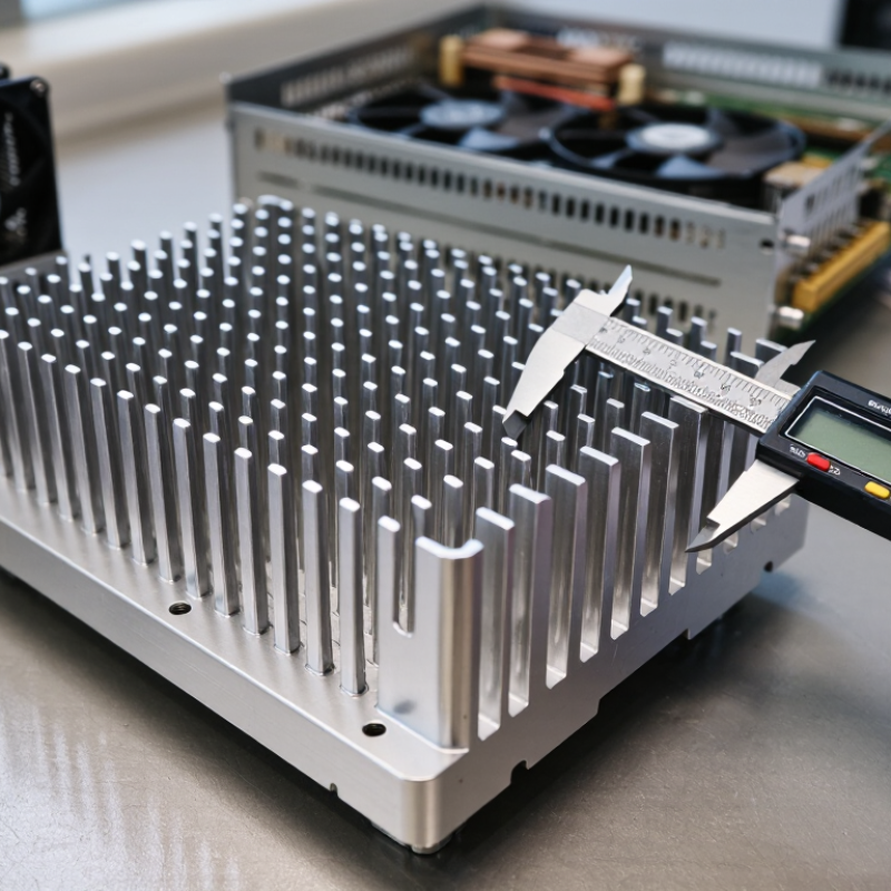
Before choosing an aluminium heatsink profile, define the actual heat load. Start with the component’s maximum power, not its typical rating. Add nearby losses from voltage regulators, memory, or lighting modules. A 60 W device may require a heatsink rated for 75 W under real conditions.
Measure the enclosure temperature, airflow, mounting direction, and allowable component temperature. ASHRAE TC 9.9 recommends 18–27°C inlet air for common data-centre equipment, but enclosed industrial systems can operate much hotter. The U.S. Department of Energy reports that cooling can represent roughly 7–30% of data-centre electricity use, showing why thermal efficiency deserves early attention. In practice, I check the thermal path: interface material, mounting pressure, base thickness, and fin exposure. A high-fin profile cannot compensate for poor contact.
Calculate the required thermal resistance with this formula: Rθ = (Tj,max − Ta) ÷ Q. If the junction limit is 100°C, ambient temperature is 40°C, and heat load is 60 W, the maximum resistance is 1.0°C/W. Leave a safety margin. Ten to twenty percent is useful, though it may be insufficient in dusty or sealed environments. I have seen designs pass laboratory tests and fail after installation. That is the uncomfortable part. Verify performance with thermocouples, controlled airflow, and steady-state testing. Datasheets help, but measured conditions matter more.
Define the Heat Dissipation Requirements
How to Choose the Right Aluminium Heatsink Profile?
Compare Aluminium Heatsink Profile Designs
Choosing a heatsink profile starts with the heat load, not appearance. Extruded aluminium profiles suit steady loads and moderate budgets. Their straight fins are easy to manufacture, but narrow channels may collect dust. ASM Handbook, Volume 2, lists 6063 aluminium thermal conductivity near 200 W/m·K, depending on temper and testing conditions. That number helps, but it does not predict the whole assembly.
For natural convection, tall vertical fins usually outperform short horizontal fins. ASHRAE Handbook—Fundamentals places typical free-air convection coefficients around 5–25 W/m²·K. Airflow matters more than many drawings suggest. Forced-air designs can use tighter fins, while bonded-fin profiles offer greater surface area with less material. Skived fins are useful for compact spaces, though their thin edges can bend during installation. I have seen a high-conductivity profile underperform because its mounting pressure was uneven.
Check the base thickness, fin spacing, airflow direction, and contact resistance. A 2 mm base may work for a small LED module, but a power converter often needs more spreading capacity. Aluminium Association industry data also shows strong use of 6063 in architectural and formed applications, supporting its practical availability. Still, alloy availability is not thermal proof. Measure the temperature at the component case, heatsink base, and exhaust air. Small errors remain possible, especially when testing in an open laboratory instead of the final enclosure.
How to Choose the Right Aluminium Heatsink Profile?
Selecting the correct size starts with heat, not appearance. Calculate the device’s power loss in watts, then define the highest acceptable temperature. For example, a 60-watt component operating at 85°C in a 25°C room allows 1°C/W total thermal resistance. Subtract the interface and case resistance before choosing the profile. A larger surface area usually improves heat transfer, but airflow matters greatly. The U.S. Department of Energy’s Solid-State Lighting reports show that lower junction temperatures support better efficiency and longer operating life. That principle also applies to power electronics.
Profile height, fin spacing, and orientation change real performance. Narrow fins may work well with natural convection because warm air can rise between them. Dense fins can perform poorly without forced airflow. A 100 mm profile is not automatically better than a 60 mm profile. Test conditions matter. I have seen compact profiles outperform larger ones when mounted vertically with clear air access. Yet, calculations can still miss contact pressure, dust, or uneven mounting. That is where engineering judgment becomes necessary.
Tips: Leave space above the fins. Keep the base flat. Check the supplier’s thermal-resistance data under similar airflow conditions. If the result is close to the limit, choose more surface area or add airflow. Do not trust catalog values blindly. Measure the case temperature during realistic operation.
Material selection determines how efficiently a heatsink moves heat away from a component. Common extrusion alloys such as 6063 typically offer thermal conductivity near 200 W/m·K, while 6061 is often closer to 167 W/m·K. These values come from published ASM and aluminium industry data. However, conductivity is only one consideration. Check tensile strength, corrosion resistance, machinability, and operating temperature. A thin profile may transfer heat well, but it can deform during installation. Strength matters.
Finish affects both performance and service life. Anodizing can improve surface hardness and corrosion protection, especially in humid equipment enclosures. ISO 7599 provides guidance for decorative and protective anodic oxidation. Do not choose a finish by appearance alone. Surface appearance misleads. Measure coating thickness and inspect contact faces for uneven buildup. The International Aluminium Institute reports that recycled aluminium requires about 5% of the energy used for primary aluminium production. Therefore, ask for recycled-content records and material traceability, not just a sustainability claim.
Manufacturing quality appears in small details. Burrs, die lines, warped bases, and inconsistent fin spacing can increase thermal resistance or complicate assembly. ASTM B221 covers aluminium extruded bar, rod, wire, profile, and tube requirements. Request dimensional reports, alloy certificates, and sampling records. A coordinate measuring machine can verify critical dimensions, while a thermal test under operating load reveals real behaviour. In practice, a visually perfect profile may still have poor flatness. That is where selection becomes less certain, and more testing is justified.
Verify installation, airflow, and thermal performance before trusting any aluminium heatsink profile. A tall fin does not guarantee effective cooling. Check the mounting surface for burrs, bowing, and contamination. Even a thin air gap can sharply increase interface resistance. Use the recommended thermal interface material and apply steady, even pressure. Uneven pressure is common.
Airflow must match the profile’s fin spacing and direction. Closely spaced fins may perform well with forced air but poorly under natural convection. Keep cables away from the inlet and outlet paths. Prevent hot exhaust air from returning to the heatsink. ASHRAE’s Thermal Guidelines for Data Processing Environments recommends 18–27°C inlet air for common equipment classes, but local hotspots can still exceed safe limits. Measure near the heatsink, not only in the room.
Use thermal resistance as a test value, not a promise. For example, removing 50 watts through a 10°C air rise requires roughly 8.8 CFM, based on air heat capacity near room temperature. Actual results vary with altitude, fan pressure, dust, and installation angle. JEDEC JESD51 test methods also show why board layout and boundary conditions affect thermal measurements. I still see engineers compare catalog values from different test setups. That comparison is imperfect. Record inlet temperature, surface temperature, airflow, load, and mounting torque during testing. Recheck after vibration and thermal cycling. Small details matter.